Final shape
Following a series of trials boiler proper took its shape...

| The trottle is hidden inside a dry pipe. It consists of a diaphragm that can be blocked using thick seewing needle.
|
| into which the steam flows from the dome.
|
Trials
The problem still to be solved is an efficient burner. It turned out, that the firebox is too confined
and the flow below the boiler barrel too much restriced. To remedy the first problem, I removed the
front-bottom wall of the firbox. But the second problem is more difficult, since there is simply not
enough place available within a resonably-to-scale diameter.
For the time beeing I decided to use gas soldering iron as a burner, at least until my model
runs on steam which is yet to come.
| 
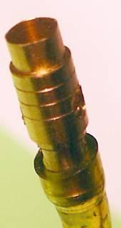
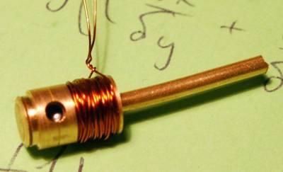
| Burner, Ř3x10. It gives an inch long, only a bit shining flame.
The nozzle inside was drilled using 0.3mm drill and then compressed with
three-jaw chuck. This works, but you cannot achieve such a momentum
of gas as is commercial burners (which are oversize). Commercial burners use a
aluminium foil in which a tiny hole is made, I should adopt the same approach
at some point.
|
| Thinking about an R/C controlled steam flow,
I fought about making an electromagnetic valve, such as shown on the right. The
ball B either sits in the nozzle closing the flow when attracted by the magnetic
field of the coil C or it is repelled by the gas pressure and opens the valve.
|
| Unfortunately it didn't work. The magnetic field of an air coil is far too weak.
|
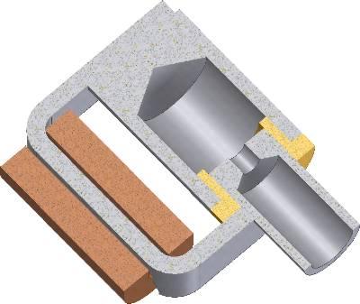
| I decided to give the idea another try. Making the valve body of mild steel (grey parts)
should help by proving a magnetic circuit that the ball would close when closing
the flow.
The ball is to be located in the cavity inside, while the gas outlet is towards the reader, in
the removed part.
|
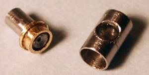
| These are the
parts of the valve ready (O.D. 3mm). I have tested the valve on compressed air,
without a coil and coil core, actuating it with a magnet. It works great, you
need just to bring the magnet within an inch distance to the valve and the ball
is attracted to the nozzle and closes the flow. It is even likely stuck.
Unfortunately I was quite at rush when making it and the socket of the ball is a
little bit uneven, so that the valve is never truly closed. Also, as it turned
our after some more investigation, the ball is always stuck to the inner
sidewall of the enclosure, so that it won't ever close the nozzle. So I decided
to leave the electromagnetic idea. |
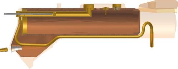
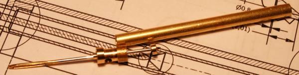 The needle goes through a slightly undersize hole made in a 0.5mm thick wall
in a steam manifold piece.
The needle goes through a slightly undersize hole made in a 0.5mm thick wall
in a steam manifold piece.
 These are the valve assembly parts. In the final version
the diaphragm divides the dry pipe, so that its location is better conrolled.
These are the valve assembly parts. In the final version
the diaphragm divides the dry pipe, so that its location is better conrolled.
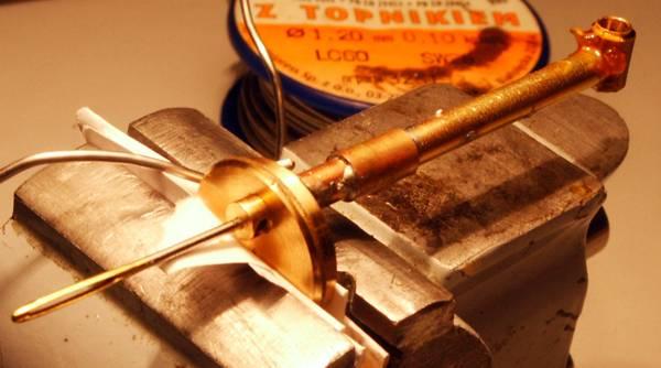
 Boiler after the steam pipes have been
soldered.
Boiler after the steam pipes have been
soldered. With the sheeting in the place.
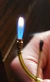
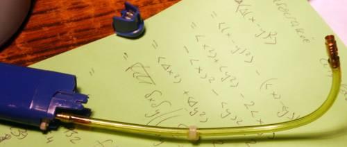 This is how the (unsuccesful) burner "assembly" looked like. I use a
cigarette lighter as a gas container, already equipped with all the valves.
Shortened a bit it will fit in the tender.
This is how the (unsuccesful) burner "assembly" looked like. I use a
cigarette lighter as a gas container, already equipped with all the valves.
Shortened a bit it will fit in the tender.
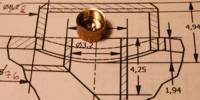
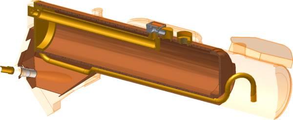 Somewhat obsolete CAD section
