(Nearly) like printed
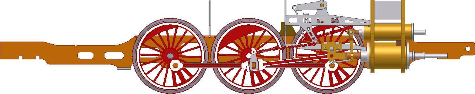
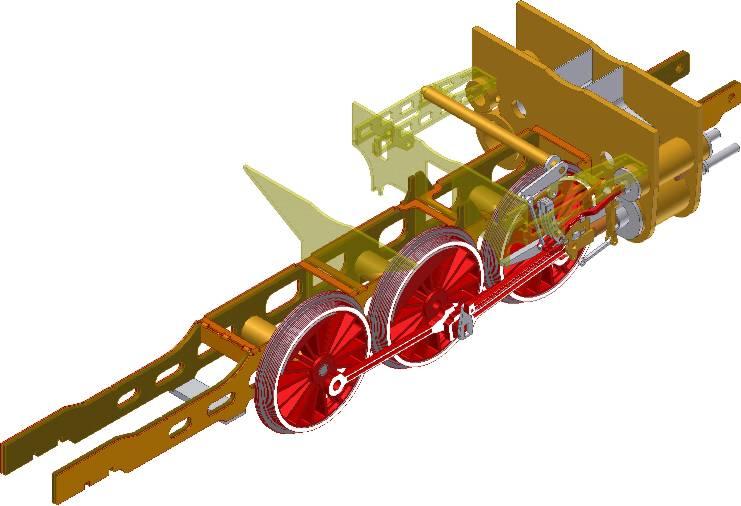 CAD model of the chassis for etched version.
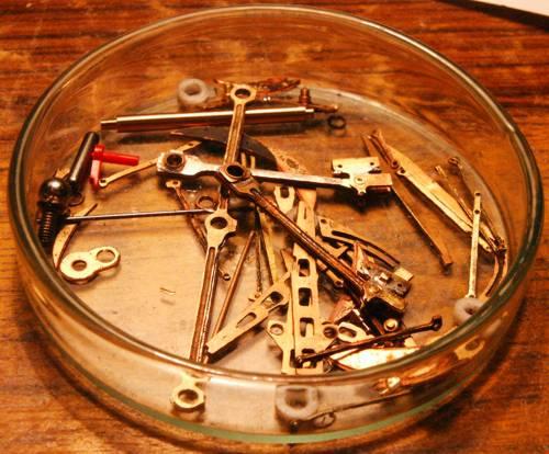
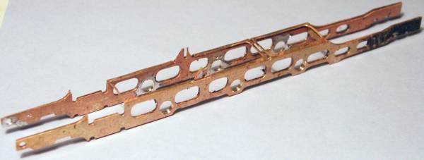 Etched frames. Made of 3 0.5mm thick brass sheets - external, bend, and two internals.
They are soldered together.
Etched frames. Made of 3 0.5mm thick brass sheets - external, bend, and two internals.
They are soldered together.
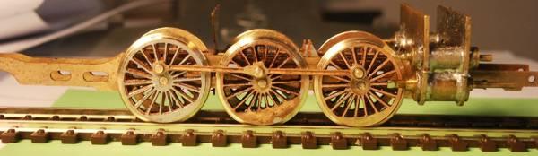
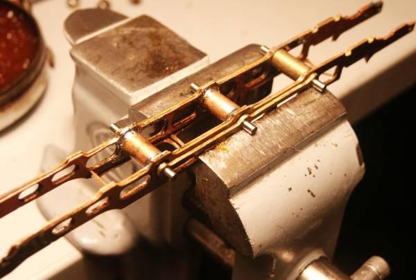 It turned out, that setting the axes parallel and in right distance is problematic.
After a few trials, I found out that I need to
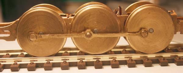 Still, the central axis is above the first and last... but at least the
mechanism is turning
freely.
Still, the central axis is above the first and last... but at least the
mechanism is turning
freely.
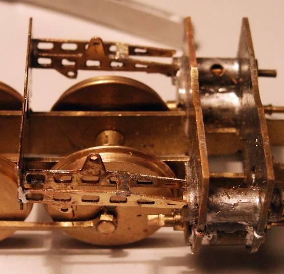 Soldered motion plate (0.5mm brass)
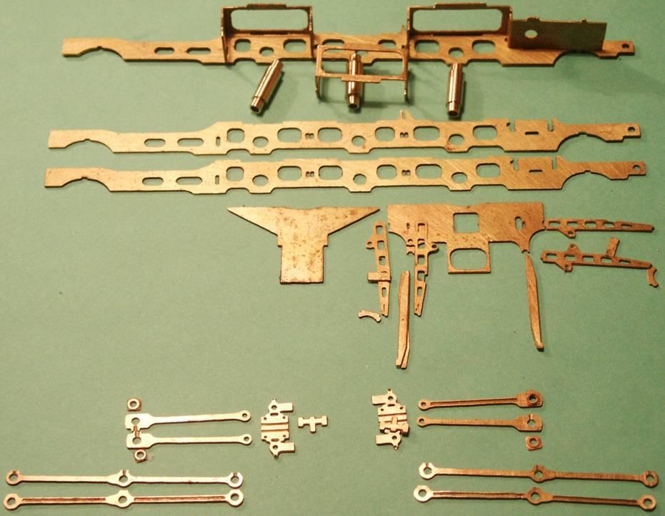
 New, final versions of the chassis elements.
 This is how I solder the coupling rod made of two layers.
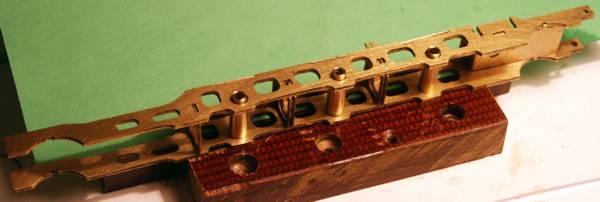 Yet another approach to building the frame.
I decided to make it of two flat pieces sheet metal per side,
supported at the right distance using bend pieces
(see the photo of all the etched elements).
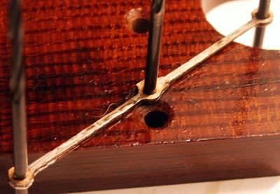
The holes etched for the side axes sleeves are made oblong,
so as to allow setting the right istance during soldering (see above).
Yet another approach to building the frame.
I decided to make it of two flat pieces sheet metal per side,
supported at the right distance using bend pieces
(see the photo of all the etched elements).
The holes etched for the side axes sleeves are made oblong,
so as to allow setting the right istance during soldering (see above).