I have laid out the valve gear using
Valve Gear simulator.
Hoping for better performance, I assumed long valve travel.
Now I'm a bit anxious that it can cause some big forces.
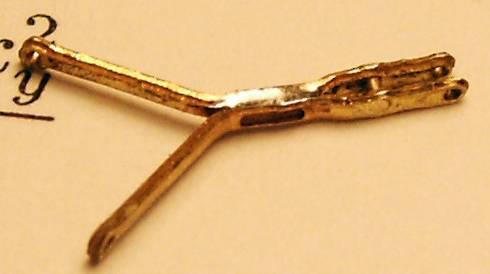
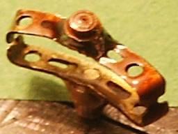
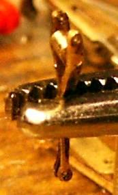 I have assembled combination lever on the valve crosshead.
In the picture just before being soldered.
I have assembled combination lever on the valve crosshead.
In the picture just before being soldered.
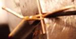
 Then I connected the union link. I have pulled the brass wire through the parts,
then cut the wire and filed it.
Then I connected the union link. I have pulled the brass wire through the parts,
then cut the wire and filed it.
 Holding link in the vice I finish the internal slot with a sharp knife.
I check the width using a wire.
Holding link in the vice I finish the internal slot with a sharp knife.
I check the width using a wire.
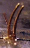
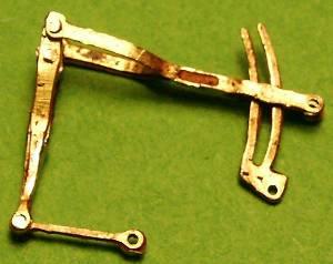
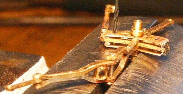
 This is how I hold the radius rod for soldering.
I set the position of the parts using two wires. I hold the part that won't be soldered,
putting a piece of correct thickness between parts.
This is how I hold the radius rod for soldering.
I set the position of the parts using two wires. I hold the part that won't be soldered,
putting a piece of correct thickness between parts.
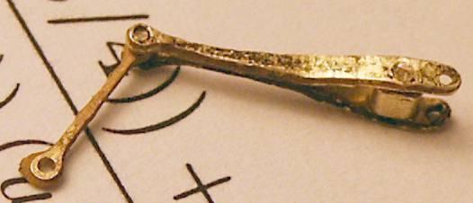
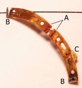
 This is how
the soldered radius rod looks like.
This is how
the soldered radius rod looks like.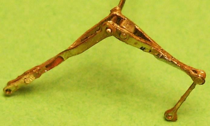 Next step -
 connecting combination lever with the radius rod.
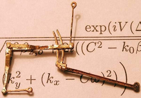 And the eccentric rod with link.
 This is how I'm going to pivot the link. Just like in prototype... probably not the best way.
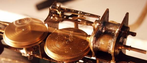
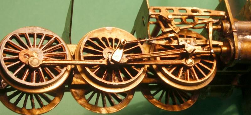
It does run!
Final version
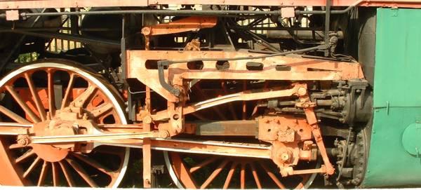 This is the prototype, kept in the Warsaw Museum of Railroading.
