


Next: About this document ...
Up: Continuum effects for the
Previous: Tables
Figures
Figure 1:
Radial PTG potentials for three values of the parameter  (see Table 8 for the complete set of parameters). The bottom
panel shows the potential for L=0, while the middle and top panels
correspond to L=4 and the PTG (1) and PTG'
(9) potentials, respectively (see text).
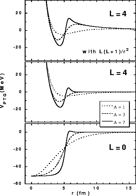 |
Figure 2:
Schematic representation of different domains of S-matrix poles in the
complex momentum and energy planes.
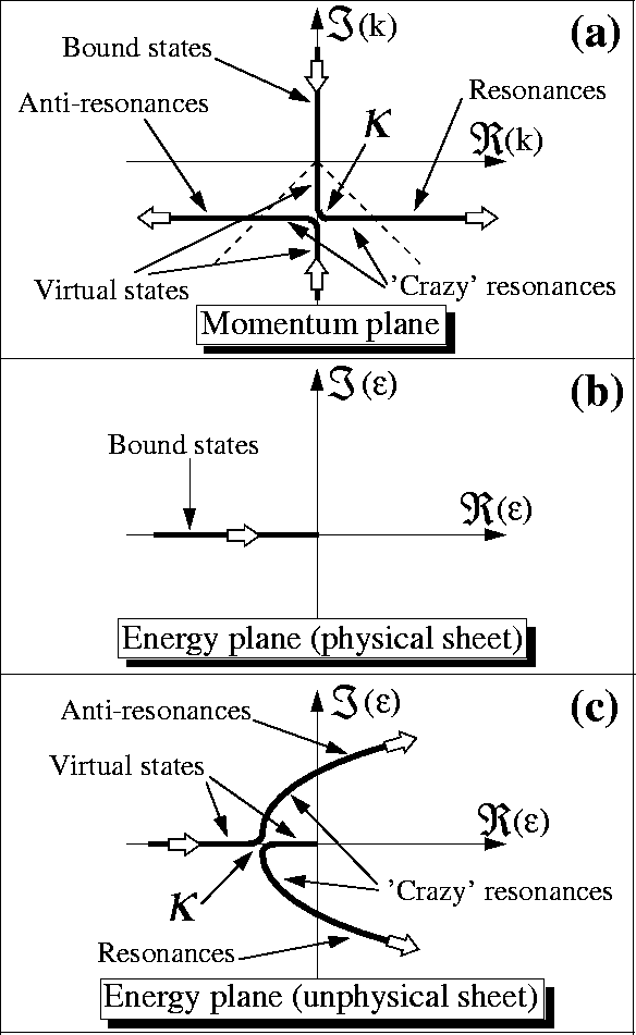 |
Figure 3:
Radial PTG wave functions of the 3s1/2 state
calculated analytically for parameters listed in Table 2.
The dotted, dashed, and solid lines correspond to resonant, virtual,
and bound 3s1/2 states, respectively.
In the inset the same wave functions are shown in the region of attractive
potential. Volume element  is included in the
definition of wave functions.
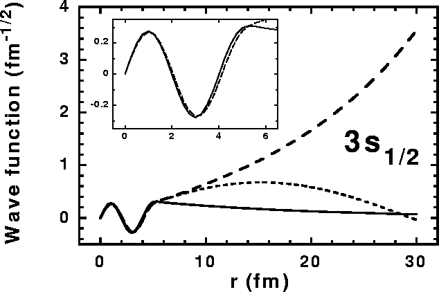 |
Figure 4:
Localization [Eq. (38)] (a) and phase shift (b) of the
s1/2 continuum PTG states. Circles denote results of numerical
calculations performed in the box of 30fm. Solid and dashed lines
show the localizations calculated analytically for scattering wave
functions normalized in the box of 30fm, and to a constant
amplitude of the outgoing wave, respectively. Arrows indicate
position of the lowest, very broad, resonance. Parameters of the PTG
potential are given in Table 2 (bound 3s1/2state).
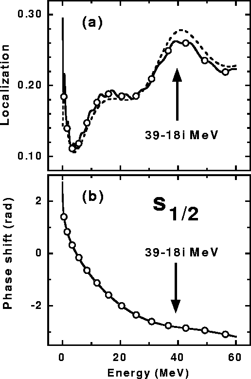 |
Figure 5:
Localization [Eq. (38)] of the HFB upper
components (dots) of the
quasiparticle states, compared with the localization of the s1/2continuum PTG states (lines).
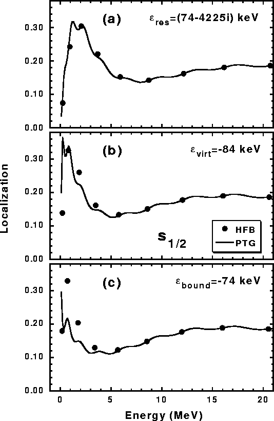 |
Figure 6:
Phase shifts of the HFB upper components (dots) of the
quasiparticle states, compared with the phase shifts of the s1/2continuum PTG states (lines).
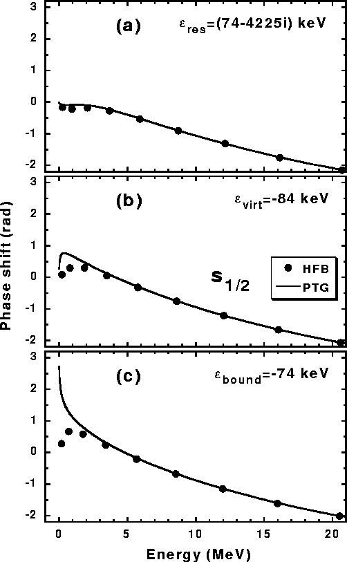 |
Figure 7:
Canonical wave functions of the 3s1/2 state, corresponding to
the three cases of the HFB calculations listed in
Table 4. The dotted, dashed, and solid lines
correspond to resonant, virtual, and bound PTG 3s1/2 states,
respectively. In the inset the same wave functions are shown in the
logarithmic scale. Volume element  is included in the
definition of wave functions.
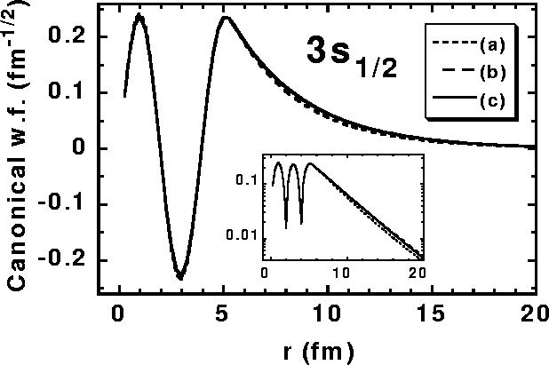 |
Figure 8:
Norms Nn of the s1/2 lower quasiparticle wave functions
 ,
corresponding to the three cases of
the HFB calculations listed in Table 4. Inset shows
the same values in the logarithmic scale.
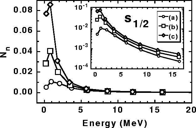 |
Figure 9:
Localization of the HFB upper components (dots) of the
quasiparticle states compared with the localization of the d3/2continuum PTG' states (lines). Upper (a) and lower (b) panels differ
by the position of the 2d3/2 resonances with respect to the top
of the centrifugal barrier, see text.
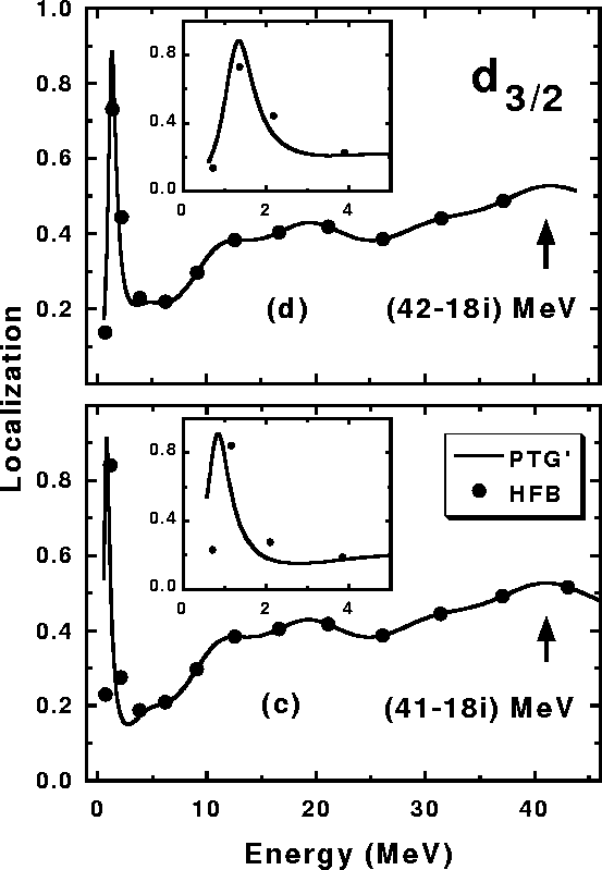 |
Figure 10:
Norms Nn of the d3/2 lower quasiparticle wave functions
 ,
corresponding to the two cases of
the HFB calculations listed in Table 4. Inset shows
the same values in the logarithmic scale.
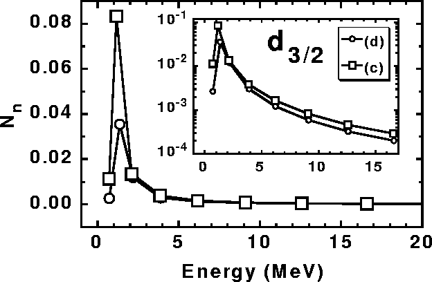 |
Figure 11:
Localizations of the HFB upper components of the d3/2quasiparticle states (dots) compared with those of the d3/2continuum PTG' states (lines). The six panels differ by the positions
of the lowest d3/2 resonance with respect to the top of the
centrifugal barrier, see text. Arrows indicate values of the
canonical energies
 of the 2d3/2canonical states.
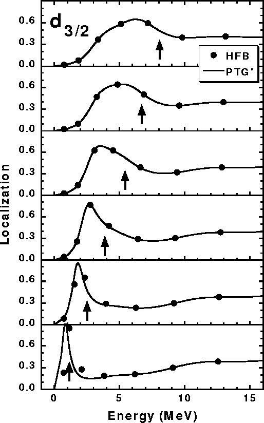 |
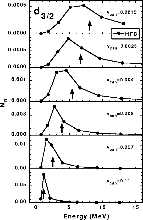
Figure 12:
Norms Nn of the HFB lower components
 of the d3/2 quasiparticle states. In each panel (similarly as in
Fig. 11), arrows indicate values of the canonical
energies
 of the 2d3/2 canonical states,
while the corresponding occupation factors
 are given
explicitly.
 |


Next: About this document ...
Up: Continuum effects for the
Previous: Tables
Jacek Dobaczewski
1999-05-16


